Program Flow: The basic structure of this program is to build a buffer (basically the live storage of information, what I originally thought would require a dedicated memory block), read the digital input much faster than it changes (if I read a 4khz-8khz signal at a rate of 125khz, I should get 30-15 reads before each change in state), then record the time between each change in state. So I’d get 30, 30, 60, 30, 30, 60 for L H L L H L H H: if that doesn’t make sense, look at manchester encoding again (in the middle of the page.). From there I convert them back into binary. Finally, I reconstruct the data into the EM4100 format, check the parity bits for data integrity, and display the resulting card number in the serial monitor.
The Program
Initialization
As a reminder, this code is based off of the DIY RFID reader from Arduino. I’ve left the copyright under edude/Arduino Forum because I’ve only technically modified it. If anyone has any more insight into the correct way of doing this please let me know! The GNU general public license can be found here.
Credit:
/* Arduino program for DIY FSK RFID Reader
* See description and circuit diagram at http://playground.arduino.cc/Main/DIYRFIDReader
* Tested on Arduino Nano and several FSK RFID tags
* Hardware/Software design is based on and derived from:
* Arduino/Timer1 library example
* June 2008 | jesse dot tane at gmail dot com
* AsherGlick: / AVRFID https://github.com/AsherGlick/AVRFID
* Micah Dowty:
* http://forums.parallax.com/showthread.php?105889-World-s-simplest-RFID-reader
* November 2011 | Modified by Ryan Baker for use with the parallax ASK modulated, manchester encoded, 125khz RFID tag | rbaker dot rpb at gmail dot com
* Copyright (C) 2011 by edude/Arduino Forum
This program is free software: you can redistribute it and/or modify
 it under the terms of the GNU General Public License as published by
 the Free Software Foundation, either version 3 of the License, or
 (at your option) any later version.
This program is distributed in the hope that it will be useful,
 but WITHOUT ANY WARRANTY; without even the implied warranty of
 MERCHANTABILITY or FITNESS FOR A PARTICULAR PURPOSE. See the
 GNU General Public License for more details.
You should have received a copy of the GNU General Public License
 along with this program. If not, see <http://www.gnu.org/licenses/>.
*/
So to start our initialization,
#include "TimerOne.h"
int ledPin = 13; // LED connected to digital pin 13
int inPin = 7; // sensing digital pin 7
int outPin = 9;
int val;
int bitlenctr = 0;
int curState = 0;
#define maxBuf 200 //reduce to 100 or so for debugging
#define streamBuf 400 // should be 2*maxBuf
#define debug 0
int raw[maxBuf];
int rawZ[maxBuf];
bool binStream[streamBuf];
int index = 0;
int indexZ = 0;
int bufnum = 0;
First thing to note is that we need to download the timer1 library if you haven’t already. This will let us set our clock speed (without having to manually change the prescalars on the PWM). We initialize variables and constants (which I’ll describe later if necessary) for input/output/counting/etc. The important points here: each constant takes precious memory on one’s microcontroller, so making something like raw or rawZ (our buffers) large is not going to be helpful. Also, Arduino input/output pins are not created equal, so be careful if you choose to change them.
setup()
void setup()
{
 Serial.begin(9600);
 Timer1.initialize(8); // initialize timer1, and set the frequency; this drives both the LC tank as well as the pulse timing clock
 // note: modify this as needed to achieve resonance and good match with the desired tags
 // the argument value is in microseconds per RF cycle, so 8us will yield RF of 125kHz, 7us --> 143kHz, etc.
    Timer1.pwm(outPin, 512); // setup pwm on pin 9, 50% duty cycle
    Timer1.attachInterrupt(callback); // attaches callback() as a timer overflow interrupt, once per RF cycle
    pinMode(ledPin, OUTPUT); // sets the digital pin 13 as output for scope monitoring
    pinMode(inPin, INPUT); // sets the digital pin 7 as input to sense receiver input signal
}
The serial communication is used for the serial display showing you the tag id. You can use whatever baud you want. Then we initialize our timer with the number of microseconds per period (see comments in code). As my tag is 125khz, I have 8. After, we output a pwm to drive the LC circuit. 512 indicates a duty cycle of 0.5 (50%) with 1023 is the highest at a duty cycle of 1 (100%). This gives a square wave. Luckily only the fundamental frequency of the square actually goes through the LC circuit (it’s the only resonant frequency) and so the circuit still works as before.
Next we have the attachInterrupt() function, which is super cool. You can create your own function (in this case, callback, described next) which runs every RF cycle. So remember I said we check the signal every period and record times between changes? This function does that.
Lastly, we set our digital pins to be inputs/outputs and the pins specified.
callback()
void callback()
{
    val = digitalRead(inPin);
    digitalWrite(ledPin, val); // for monitoring
    bitlenctr++;
    if(val != curState) {

        // got a transition
        curState = val;

        if(val == 1) {
            // got a start of cycle (low to high transition)
            if(index < maxBuf) {
                raw[index++] = bitlenctr;
            }
            bitlenctr = 1;
        }

        if(index > 1 && val == 0){
            // got transition to low
            if(indexZ < maxBuf) {
                rawZ[indexZ++] = bitlenctr;
            }
            bitlenctr = 1;
        }

    }
}
And I just found out WordPress doesn’t maintain tabs from Arduino, so I need to manually add those as spaces… anyway! We initialized our bitlenctr as zero and every time this callback runs (once per clock period) we add one to it (I’m guessing the name stands for bit length counter). We also initialized an int curState as zero previously and compare it with val, the value of our input pin. If they’re not the same, we need to do stuff. One thing we need to do is change curVal into being val, so that when this callback runs again it doesn’t fire off again (we only want it to do stuff when the state changes). Then we record the value into either raw or rawZ depending on if the input is 1 or 0 (Z stands for 0). This is how we keep track of the times between state changes (so often this number is around 30 or 60). Finally, we reset our bitlenctr counter to 1. For anyone reading this, I know the code isn’t particularly optimized, so you’ve been warned!
I’m going to skip loop() for now as it is longest and instead focus on the only other function, process_buf. Note that process_buf() should be placed at the end of the source, not after callback!
process_buf()
// process an input buffer with a valid start tag
// start argument is index to first 0 bit past prefix tag of 15+ ones
void process_buf(int start) {

    int curHByte;
    int parityTerminus[4];
    bool failed = false;
    bool willFlipIfFail = true;
    int sumParity;
    char theHex[16] = {'0','1','2','3','4','5','6','7','8','9','A','B','C','D','E','F'};
    char theCode[10];

    while(failed^willFlipIfFail){
         failed=false;
         parityTerminus[0]=0;
         parityTerminus[1]=0;
         parityTerminus[2]=0;
         parityTerminus[3]=0;
         // Loop through theCode to get our final RFID code
         for(int i = 0; i < 10; i++){
             curHByte=0;
             sumParity=0;
             //Serial.println(" ");
             // Loop through the bits corresponding to a single character
             for( int j = 0; j < 4; j++){
                 if(!willFlipIfFail){
                     binStream[start+j+i*5]=!binStream[start+j+i*5];
                 }
                 curHByte = curHByte+round(pow(2,(3-j)))*(int)binStream[start+j+i*5];
                 parityTerminus[j] = parityTerminus[j]+(int)binStream[start+j+i*5];
                 sumParity = sumParity+(int)binStream[start+j+i*5];
                 //Serial.print(binStream[start+j+i*5]);
             }
             //Serial.print(binStream[start+4+i*5]);
             //Serial.print(" and ");
             //Serial.print(sumParity%2);
             if(sumParity%2!=binStream[start+4+i*5]){
                 failed = true;
             }
             // Convert binary to hex
             theCode[i]=theHex[curHByte];
             //Serial.print(" ");
             //Serial.print(theCode[i]);
         }
         //Serial.print("\n");
         for( int i = 0; i < 4; i++){
             //Serial.print(parityTerminus[i]%2);
             //Serial.print(" and ");
             //Serial.print(binStream[start+50+i]);
             //Serial.print("\n");
             if(parityTerminus[i]%2!=binStream[start+50+i]){
                 failed = true;
             }
         }
     willFlipIfFail=!willFlipIfFail;
     }

     if(failed){
         Serial.println("\nParity failed, abort.\n");
     }
     else{
         Serial.println("\nSuccess! Your tag ID is: ");
         for(int i=0;i<10;i++){
             Serial.print(theCode[i]);
         }
     }
     Serial.println("\n");
}
First thing to note, you’ll see many lines of code commented. This was for a lazy/manual form of debugging problems (and there were many). You can uncomment them or just get rid of them and write your own if you have problems. This is when explicitly knowing the technology like we’ve been trying to do is really important because you can output various strings of bits or times or whatever and check them. If you’ve done little electronics/coding debugging, this may be difficult.
Ok, so this function is for processing a set of binary numbers to check for a valid tag. We’ll have already found the start of the tag (the first set of at least 9 ones) and so this function sorts the data according to the EM4100 protocol, checks data integrity, and outputs the tag id. If you were making a security lock or something, all you would need to do from here is check that tag against a pre-made list of tags (strcmp, be careful though, it may output 0 when true? You’ll need to double check yourself) and if there was a match, output the signal to another pin to unlock whatever.
To start, we initialize variables, an important one being theHex. When we get some number, say 1011, we convert it to a decimal number curHByte (current half byte), in this case 11, then use that as an index to theHex to get the corresponding hex character, in this case B. We record these sets of hex chars into theCode.
The while loop is here to do two checks on the data. It XORs ‘failed’ with ‘willFlipIfFail,’ which is opaque, I know, but I wasn’t able to reliably check if the binary was right-side-up or upside-down, that is, if it had ones for zeros or vice versa, so I check both cases! I start by assuming the binary stream I have is right, and if the data check fails (setting failed=true), I flip all the bits (then setting willFlipIfFail to its opposite [this is important for the XOR, don’t set to false] so I don’t do this again) and recheck the data. I then do a loop through the ten characters I intend to pull from the binary (hence the i loop from 1 to 10). We remember that there are 4 bits representing the hex, so we convert those to decimal in our j loop. Remember our last 4 parity bits of the tag though? They need to count up the rows for their parity. Thus we need to keep track of those parity bits (parityTerminus) all of the time. We also need to sum the bits in our current j loop (that is, along columns) for checking their parity. If that binary sum (integer sum modulo 2) doesn’t equal the corresponding parity bit, we’ve failed. Otherwise, write it into the code. Once this i loop is done, check the parityTerminus numbers to see if they also pass. If all have passed, failed should be false and we exit the loop. Depending on if you failed or succeeded you get a different message. Failed obviously just tells you it didn’t work, succeed and you read out the tag.
Now finally, the microcontroller’s main program loop()
loop()
void loop()
{
   if(index >= maxBuf) {
       // Serial.print("got buf num: ");
       // Serial.println(bufnum);
       if(debug) {

          for(int i = 0; i < maxBuf;i++) {
              Serial.print((int)raw[i]);
              Serial.print("/");
          }
          Serial.println("///raw data");
          delay(2000);

          for(int i = 0; i < maxBuf;i++) {
              Serial.print((int)rawZ[i]);
              Serial.print("/");
          }
          Serial.println("///rawZ data");
          delay(2000);
       }
       // analyze this buffer
       // first convert pulse durations into raw bits
       int tot1 = 0;
       int tot0 = 0;
       int tote = 0;
       int totp = 0;
       raw[0] = 0;
       rawZ[0] = 0;
       for(int i = 1; i < maxBuf; i++) {
           int v = raw[i];
           int vZ = rawZ[i];

           // Check length of high bits
           if(v > 10 && v < 22) {
               raw[i] = 1;
               tot0++;
           }
           else if(v > 21 && v < 27) {
               raw[i] = raw[i - 1];
               totp++;
           }
           else if(v > 26 && v < 50) {
               raw[i] = 2;
               tot1++;
           }
           else {
               raw[i] = 101; // error code
               tote++;
           }

           // Check length of low bits
           if(vZ > 10 && vZ < 22) {
               rawZ[i] = 1;
               tot0++;
           }
           else if(vZ > 21 && vZ < 27) {
               rawZ[i] = rawZ[i - 1];
               totp++;
           }
           else if(vZ > 26 && vZ < 50) {
               rawZ[i] = 2;
               tot1++;
           }
           else {
               rawZ[i] = 101; // error code
               tote++;
           }

       }

       // Test for whether starting bit is 1 or 0
       int hStart=0, lStart=0;
       for(int i = 0; i < maxBuf ; i++){
           if(raw[i]==2){
               hStart=i;
               break;
           }
       }
       for(int i = 0; i < maxBuf ; i++){
           if(rawZ[i]==2){
               lStart=i;
               break;
           }
       }
       int curBit;
       if(hStart<lStart){
           curBit=1;
       }
       else{
           curBit=0;
       }

       // Convert time lengths to binary
       int binIndex = 1;
       for(int i = 3; i < maxBuf; i++) {
           if(raw[i]==1&&rawZ[i-2]==1){
               binStream[binIndex]=curBit;
               // Serial.print((int)binStream[binIndex]);
               binIndex++;
           }
           else if(raw[i]==2&&rawZ[i-2]==1){
               binStream[binIndex]=curBit;
               // Serial.print((int)binStream[binIndex]);
               binIndex++;
               curBit=1-curBit;
               binStream[binIndex]=curBit;
               // Serial.print((int)binStream[binIndex]);
               binIndex++;
           }
           else if(raw[i]==1&&rawZ[i-2]==2){
               curBit=1-curBit;
               binStream[binIndex]=curBit;
               // Serial.print((int)binStream[binIndex]);
               binIndex++;
           }
           else if(raw[i]==2&&rawZ[i-2]==2){
               curBit=1-curBit;
               binStream[binIndex]=curBit;
               // Serial.print((int)binStream[binIndex]);
               binIndex++;
               curBit=1-curBit;
               binStream[binIndex]=curBit;
               // Serial.print((int)binStream[binIndex]);
               binIndex++;
           }
           else{
               Serial.println("\nErrors in binary stream (a few of these messages are fine): ");
               Serial.print(raw[i]);
               Serial.println(" ");
               Serial.print(rawZ[i-2]);
           }
       }
       delay(2000);
       // next, search for a "start tag" of 9 high bits in a row
       int samecnt = 0;
       int start = -1;
       bool lastv = 0;
       for(int i = 0; i < streamBuf; i++) {
           if((binStream[i] == lastv)&&(binStream[i] == 1)) {
               // inside one same bit pattern, keep scanning
               samecnt++;
               // Serial.print(samecnt);
           }
           else {
               // fewer than 9 1s, so not a valid tag, keep scanning
               samecnt = 1;
               lastv = binStream[i];
           }
           // got new bit pattern
           if(samecnt >= 9) {
               // got a start tag prefix, record index and exit
               start = i;
               // Serial.println("\nFound the ones!\n");
               break;
           }
       }
       // if a valid prefix tag was found, process the buffer
       if(start > 0 && start < (streamBuf - 64)) { //adjust to allow room for full dataset past start point
           process_buf(start+1);
       }
       else {
           Serial.println("no valid data found in buffer");
       }
       if(debug) {
           for(int i = 0; i < maxBuf; i++) {
               Serial.print((int)raw[i]);
               Serial.print("/");
           }
           Serial.print("///\nbuffer stats: ones: ");
           for(int i = 0; i < maxBuf; i++) {
               Serial.print((int)rawZ[i]);
               Serial.print("/");
           }
           Serial.print("///\nbuffer stats: zeroes:");
           Serial.print(tot0);
           Serial.print("/ones:");
           Serial.print(tot1);
           Serial.print("/prevs:");
           Serial.print(totp);
           Serial.print("/errs:");
           Serial.println(tote);
           delay(1000);
       }
       // start new buffer, reset all parameters
       bufnum++;
       curState = 0;
       index = 0;
       indexZ = 0;
   }
   else {
       delay(5);
   }
}
This is big but not that difficult to understand. We process the data if the buffer has been filled, otherwise we simply continue calling the callback to fill the buffer (this goes on in the background). The first debug check simply outputs to the serial monitor if you chose to do so earlier. The first i loop simply threshold the “imperfect” times (15 will sometimes be 14 or 16, or 30 might be 28 or 31,etc) to a value 1 or 2, representing the lengths of the highs or lows in a discrete way. After that, there’s a section in the code which tries to determine if our stream started on a one or zero, which can help but still isn’t robust. Any errors in the first few bits can ruin this, and sometimes they do. Then our next for loop we convert the times into the original binary. This is particularly tricky because a 2 in our time vectors adds half a period to our binary vector, which can sometimes result in adding two values to the binary stream… but sometimes not! So the binary stream needs a separate index from i. Our result also depends on the combination of lows and highs. So we can have a pair (raw[i], rawZ[i-2]) (the minus two is because of the strange way I indexed them to start with) {(1,1), (2,1), (1,2), (2,2)}, which correspond to adding {(curBit), (curBit, 1-curBit),(1-curBit),(1-curBit,curBit)} (be careful with (2,2) as the second bit added is the same bit that it starts with, which in the code progresses as 1-curBit and then 1-curBit again to get to the previous state), respectively, to the binary stream. Not intuitive by any measure, but it works! We delay just for stability, then we do a simply check for at least 9 ones (or zeros). If it passes, we call process_buf at the index which corresponds to the start of the 9 ones, and if not, continue down the loop. If debugging is on, it shows more parameters. Lastly, we reinitialize the buffer indices. The else statement at the very end is from the very first if statement where we checked it we had filled the buffer. If we didn’t, we waited a little with this delay and then rechecked (with callback() running in the background).
And that’s it! After running this I was able to identify my tag as 08003D8D7B, which is what we found in my very first post. Now that I’ve finished this part of the project, I’m going to update my original goals now that I have a greater understanding of the technology:
- To gain a minimal, procedural understanding of how to read RFID tags (Day 1).
- To gain a quantitative understanding of the science behind reading RFID tags and to make my own original design for reading them.
- Final Project: To design and construct a device capable of reading a tag on a different system where the parameters are unknown (a tag not provided by parallax and whose parameters are different than the one I currently have).
These goals are not actually different than before, they’re just reframed in a more cohesive manner. The first two are now finished and now I need to figure out how to read a card another card of mine. Testing it quickly on my current setup revealed that it may not even be a 125khz (or any LF) device but may be a 13.56 MHz device instead. I’m guessing this because when I place this card near the coil it didn’t even change the amplitude. Yet there is something strange in that it responds as I’m moving to or from the coil… so I’m not sure. Anyway, I don’t think I have any more free days this year to pursue this project, but I hope to report on something interesting by early next year. Until then, I have one or two other interesting, unrelated projects to report on before the year’s end, so stay tuned. Thanks for reading!
Edit: There are hints that my other card really is 13.56Mhz. I made a resonant circuit at ~1MHz, used a function generator to generate the signal, used an oscilloscope to monitor the resulting modulation, and the card changed the waveform somewhat when brought near the inductor. So now to get into 13.6MHz…


 ), it extends the voltage by another half clock period… halving the frequency.
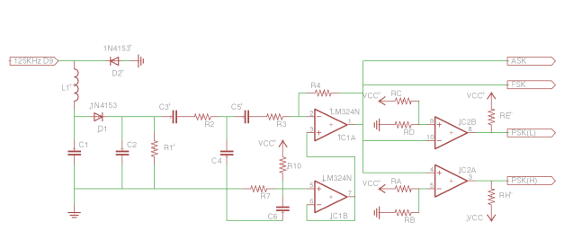
 , and the lower gate will be input to the inverting input (pin 10) of my comparator, with a similar gate as before but with different resistor values. The values of the resistors that work for the voltages I stated will be listed below. Lastly, the resistors right before the PSK outputs are pull-up resistors.
 H
H after the capacitor, a resistor
  between in the inverting input and output for a gain of
  ). Remember this flips your signal!
 different numbers. So, the tag transmits hexadecimal! We know a priori that there are 10 hex characters that represent the tag (see my first post). From the site, we find that the first 2 are the version/customer ID, and the last 8 make up the tag’s individual identification. Also, from the site, we know that the endianness is big, that is, most significant bits are transmitted first.
 last parity bit B(n),
  , is the binary sum
  ). The very last bit is 0. You can convince yourself that with this configuration you can not have any run of 9 or more ones other than at the beginning of the tag.
 4 4 2 4 6 2 3 6 4 4 2 6 2 4 7
 6 3 4 5 6 6 6 4 3 1 3 2 2 3 4
 4 4 4 4 4 2 5 4 4 4 2 6 4 4 5
 4 5 4 3 6 4 6 4 5 3 5 4 2 1 4
 .)
.)
 and our modulated signal be
  (possibly acquiring phase
  from the LC process), where
  is the underlying binary signal.
 ). Green: The modulated signal is inverted with a gain of 1. Blue: The original signal and the inverted signal are added together, with coefficients given by
  . The coefficients are chosen such that the amplitude for one of the modulated amplitudes is 0V. The signal then is rectified and low pass filtered.
 . Mathematically this is equivalent, but in electronics these are two separate operations. I first use an inverting op-amp with gain 1 to invert my signal (see Figure 2, green,
  ), then I use a mixer (blue, up until the diode) to add the signals to each other. The first step is obvious (
 ). The second is simple enough (try to do the math yourself, remembering op amp golden rules. Be particularly careful as you look at the voltages across the inputs and outputs; the middle is grounded, and you are “traveling” along only one direction) and the result is
  or
or (1)
(1) terms necessary. Using the addition formula we get
 ). Expand both sine and cosine for the
 (depending on the rectification, filtering), and we end with (assuming
  , which should be fine for either the 1 or 0 part of M(t))
 (2)
(2) and
and  Volts, I should have
 (3)
(3) .
. and
and  (
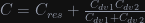
( obviously being 125khz). I arbitrarily chose something in the nF range for one of the capacitors, then the rest fit into place.
  ,
,  ,
,  .
. .
. s. So I’d like a rising edge from 0 to 5V where the full rise occurs over half the period of our original signal. At worst. Now, turns out there is a number which represents this: the slew rate. It is the maximum change in voltage per time that a device can produce. So I need a slew rate of
  . Because of this, I can’t grab a standard LM741. So I looked at the op-amps in stock and chose the LT1022, which has a slew rate of
  .
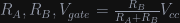
. V, so I need
  . I have pots with
  turns at
  , so I’ll chose a
  . These will be fine tuned differently for different configurations. As for
  ,
,  , these were picked rather arbitrarily. I just started putting in combinations of R’s and C’s and saw what worked. So I have
  and
and  .
.
